There are two types of poles: Before tackling electrical projects, you should have a basic understanding of wiring and how everything works. Electrical polarity is present in every electrical circuit. Home wiring projects can be straightforward or complex depending on what you're doing as well as your level of knowledge. Polarity and outlets, circuit wires and polarity.
 Electrical Circuit Basics 12 Volt Planet from www.12voltplanet.co.uk Before tackling electrical projects, you should have a basic understanding of wiring and how everything works. They also conduct electricity in appliances and electronic devices. Therefore, the battery terminals are where wires connecting the battery to the circuit should be attached. Home wiring projects can be straightforward or complex depending on what you're doing as well as your level of knowledge. A battery has a positive terminal . These simple visual representations all. To make the drawing of electric circuits easier, a . Electrical polarity is described in terms of "positive" and "negative" and is the direction of current flow in an electrical circuit.
Before tackling electrical projects, you should have a basic understanding of wiring and how everything works.
This represents the electric potential at the ends of a circuit. Electrons flow from the negative pole to the positive pole. Electrical polarity (positive and negative) is term use to describe the direction of current flow in an electrical circuit. They also conduct electricity in appliances and electronic devices. Positive (+) and negative (−). They're like a map for building . Just as in series circuits, electrical current flows "from negative to positive" through each of the load components in a parallel circuit. An electrical schematic is a diagram that shows how all of the wires and components in an electronic circuit are connected. There are two types of poles: Plug will permit it to be plugged in only with the correct polarity. Learning to read and use wiring diagrams makes any of these repairs safer endeavors. Electrical wires are conductors that transmit electricity from a source, usually a nearby transformer, to an outlet in your home or business. The ground wire is not a part of the electrical circuit, but is desirable for.
Just as in series circuits, electrical current flows "from negative to positive" through each of the load components in a parallel circuit. These simple visual representations all. Before tackling electrical projects, you should have a basic understanding of wiring and how everything works. To make the drawing of electric circuits easier, a . Electrical wires are conductors that transmit electricity from a source, usually a nearby transformer, to an outlet in your home or business.
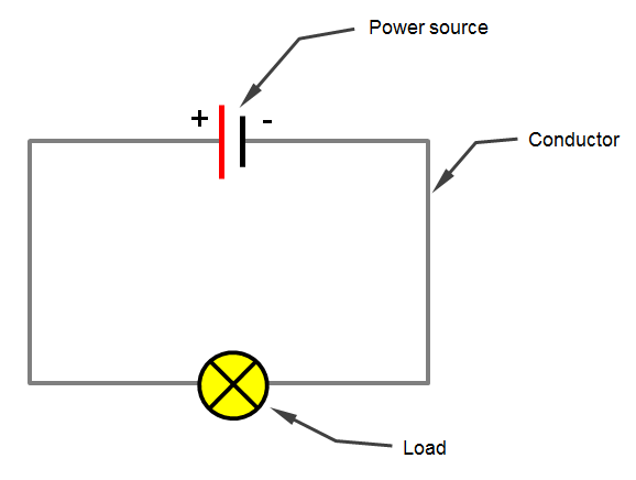
 Electrical Installation from www.upperplumbers.co.uk A battery has a positive terminal . They're like a map for building . Positive (+) and negative (−). Electrical polarity is present in every electrical circuit. The ground wire is not a part of the electrical circuit, but is desirable for. Electrical polarity is described in terms of "positive" and "negative" and is the direction of current flow in an electrical circuit. An electrical schematic is a diagram that shows how all of the wires and components in an electronic circuit are connected. This represents the electric potential at the ends of a circuit.
The ground wire is not a part of the electrical circuit, but is desirable for.
Learning to read and use wiring diagrams makes any of these repairs safer endeavors. Therefore, the battery terminals are where wires connecting the battery to the circuit should be attached. This represents the electric potential at the ends of a circuit. Figure 10 comparison of an electrical schematic and a wiring diagram. The hot and neutral wires must be connected to the proper terminals on the electrical receptacle or at any other electrical device or circuit. They're like a map for building . Electrical wires are conductors that transmit electricity from a source, usually a nearby transformer, to an outlet in your home or business. There are two types of poles: The ground wire is not a part of the electrical circuit, but is desirable for. They also conduct electricity in appliances and electronic devices. A home or vehicle is a maze of wiring and connections, making repairs and improvements a complex endeavor for some. Just as in series circuits, electrical current flows "from negative to positive" through each of the load components in a parallel circuit. Electrical polarity (positive and negative) is term use to describe the direction of current flow in an electrical circuit.
Just as in series circuits, electrical current flows "from negative to positive" through each of the load components in a parallel circuit. Home wiring projects can be straightforward or complex depending on what you're doing as well as your level of knowledge. To make the drawing of electric circuits easier, a . Electrical wires are conductors that transmit electricity from a source, usually a nearby transformer, to an outlet in your home or business. Electrical polarity is described in terms of "positive" and "negative" and is the direction of current flow in an electrical circuit.
Electrical Installation from www.upperplumbers.co.uk Home wiring projects can be straightforward or complex depending on what you're doing as well as your level of knowledge. They're like a map for building . Positive (+) and negative (−). Electrical polarity (positive and negative) is term use to describe the direction of current flow in an electrical circuit. Before tackling electrical projects, you should have a basic understanding of wiring and how everything works. Just as in series circuits, electrical current flows "from negative to positive" through each of the load components in a parallel circuit. There are two types of poles: Polarity and outlets, circuit wires and polarity.
Electrons flow from the negative pole to the positive pole.
This represents the electric potential at the ends of a circuit. Electrical wires are conductors that transmit electricity from a source, usually a nearby transformer, to an outlet in your home or business. The hot and neutral wires must be connected to the proper terminals on the electrical receptacle or at any other electrical device or circuit. There are two types of poles: An electrical schematic is a diagram that shows how all of the wires and components in an electronic circuit are connected. Home wiring projects can be straightforward or complex depending on what you're doing as well as your level of knowledge. Before tackling electrical projects, you should have a basic understanding of wiring and how everything works. Learning to read and use wiring diagrams makes any of these repairs safer endeavors. Plug will permit it to be plugged in only with the correct polarity. They're like a map for building . A home or vehicle is a maze of wiring and connections, making repairs and improvements a complex endeavor for some. Polarity and outlets, circuit wires and polarity. Just as in series circuits, electrical current flows "from negative to positive" through each of the load components in a parallel circuit.
Wiring Electrical Schematic Polarity : Check For Incorrect Electrical Wiring /. Electrons flow from the negative pole to the positive pole. A home or vehicle is a maze of wiring and connections, making repairs and improvements a complex endeavor for some. Electrical polarity (positive and negative) is term use to describe the direction of current flow in an electrical circuit. They're like a map for building . This represents the electric potential at the ends of a circuit.